Ham Radio - Camera -
Computer - F8HP - UV5R - Baofeng - Pofung
Add an Internal Fan & Thermostat
to your mobile transceiver
by: John 'Miklor'
K3NXU
Add an Internal Fan & Thermostat
to your mobile transceiver
by: John 'Miklor'
K3NXU
|
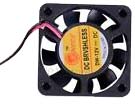
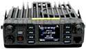
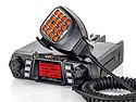
Preface Although the example shown here was installed in a BTech 5001, the information, components and templates can be applied to add additional cooling to any transceiver. Project One of the upgrades to the BTech UV5001 Gen 3 was the addition of an internal cooling fan. What is described below is how you can add your own thermostat controlled cooling fan to a Gen 1 or 2 radio for under $10. I also have a Gen 3, and found it to run quieter by simply replacing the existing fan with the larger one. This project is not limited to just this model radio, but to any radio that needs a little additional cooling. Parts List - CPU cooling fan (40mm x 10mm) - Ferrite Bead (3 x 4.5 x 10) - KSD-01F H60C - Drill bit - Screw The heart of the project is the CPU fan. These small fans found in many laptops and because of their mass production, are readily available on eBay for under a dollar. The project uses the standard size is 40mm x 10mm cooling fan. They are small, very quiet, and push a lot of air. I selected this fan over the smaller 2.5mm fan due to the lower fan noise.
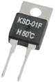
The thermostat is a KSD-01F H60C. These are 12 volt thermostats that are available in various temperatures for around $2. I personally prefer the H60C (140F), but the choice is yours. You don't want the value to be too low, or the fan may never shut off. Too high and it may never turn on. The thermostat closes at 60C (140F), and opens back up when the temperature cools down to 55C (131F). Lower values may kick in a few seconds sooner but tend to run even after the radio has cooled down. I like the 60C-70C range. When selecting the desired value, consider the temperature of the car on a hot day. Be very careful when purchasing these. There is an identical looking component labeled D60C where the contacts are N.C. (normally closed). Make sure you get the H60C, where the contacts are N.O. (normally open). You only want the contacts closed when the thermostat is hot.
The third component is the Ferrite Bead. This prevents any fan RF/static from entering into the receiver. The size used in the Gen 3 radio is 3 x 4.5 x 10mm. I used 2 x 4 x 8mm as they were readily available. The 2mm center only allowed one wire to pass through, so I used one each wire. Good practice is to place them as close to the fan as possible. References: Ferrite Bead EMI / RFI
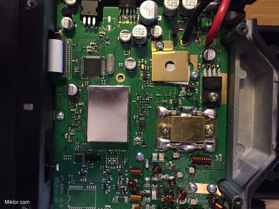
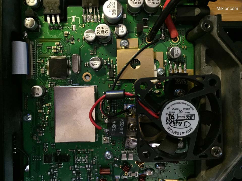
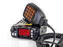
Below are before and after pictures of the inside of a UV5001. There are no components that need to be moved as the fan will sit nicely about 3/16" above the finals.
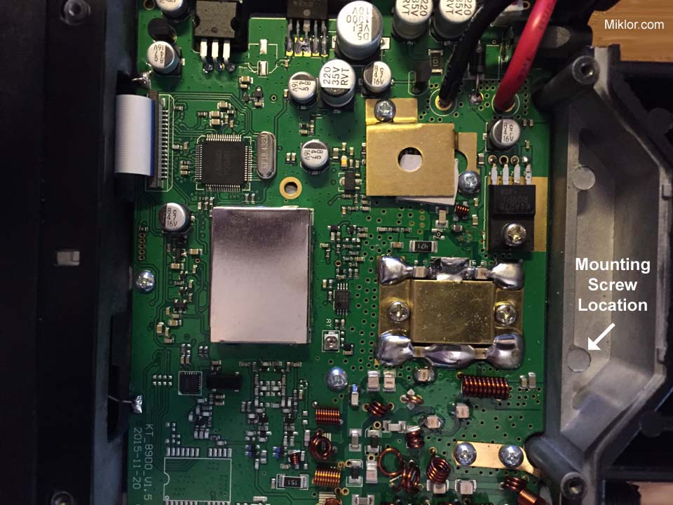
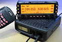
The Process The first thing needed is to drill a mounting hole in the aluminum frame. The picture below shows where the fan is mounted on the Gen 3. I wouldn't recommend drilling a hole greater than 1/16" to start, as the mounting holes in the fan are only 1/8" Be extremely careful of metal shavings as they don't play well together with surface mount components.
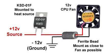
Visual Schematic
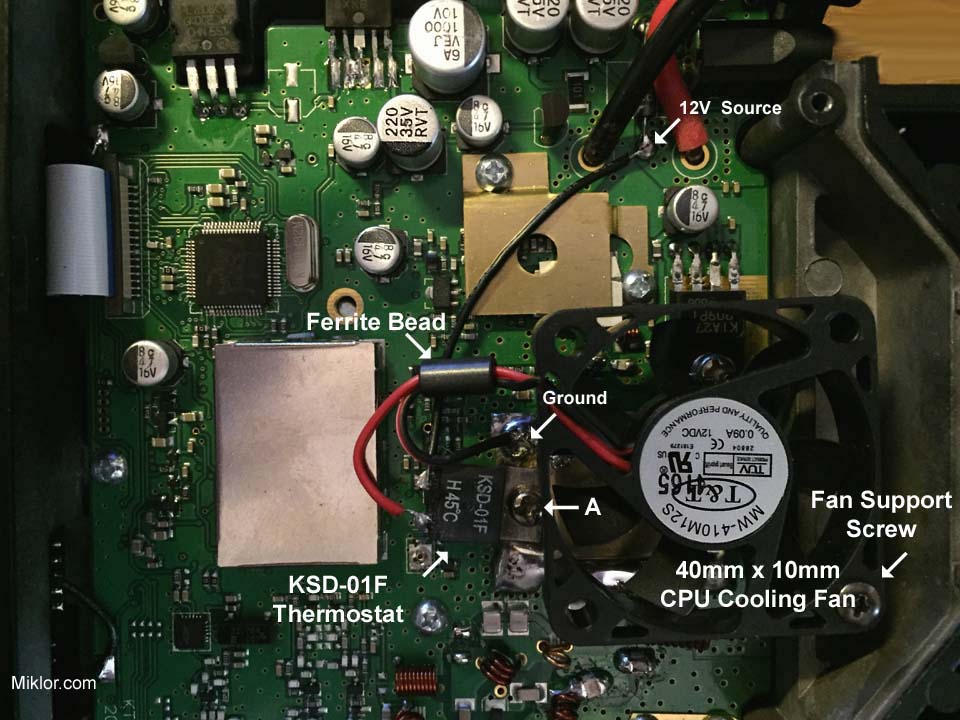
The steps I used were the following: - Unscrew the left mounting screw of the RF module. (Labeled A below) - Mount the top of the thermostat to that location and replace screw. This will be the heat source for the thermostat as well as the needed Ground connection - Connect a piece of insulated stranded wire from the 12V Source to one leg of the thermostat. - Place the ferrite Bead over the two wires running from the fan as shown below. - Connect the Red wire from the fan to the other leg of the thermostat. - Connect the Black wire from the fan to ground. - Screw the fan into place. Note: The airflow of the fan should be pulling the air away from the RF component. You want to draw the heat away, not blow it back on the module.
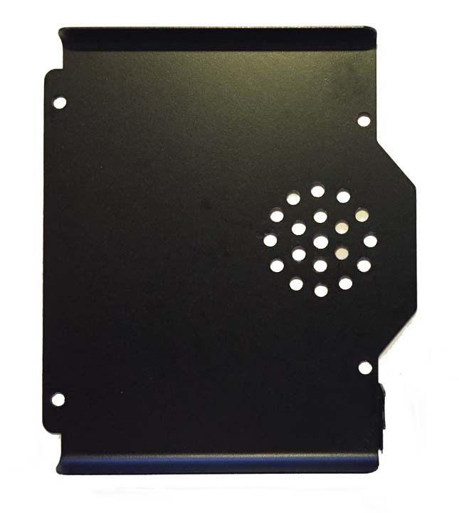
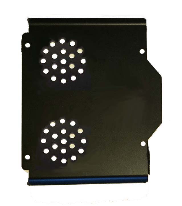
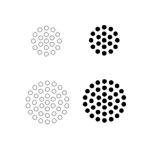
When the transmitter is keyed, the fan should turn on after approx 20 seconds. The fan will continue to run until the cool down threshold is met. This could take several minutes after the last transmission. Bottom Cover and Template Now, here's an extra step I performed on mine to help the heat sinks. I perforated the bottom cover to assist with venting some of the heat. I started with the circular pattern template found HERE. To center the pattern directly over the fan, I measured one inch from the edge of the lid. That should be the center of the fan. I started with a 1/16 drill bit after using the template with a center punch, and finished with an 11/64" drill bit. (Measure twice, cut once) . I tried two different configurations. The first was to drill holes directly above the fan. It worked extremely well, but the fan noise was elevated slightly as you could hear the fan blowing through the holes. On my other 5001, I drilled the same pattern twice, but toward the front of the radio. The cooling was also excellent with no fan noise.
|
|


