Ham Radio - Camera -
Computer - F8HP - UV5R - Baofeng - Pofung
Changing the Fan Thermostat
in your mobile transceiver
by: John 'Miklor'
Changing the Fan Thermostat
in your mobile transceiver
by: John 'Miklor'
|
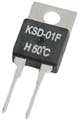
Project If your transceiver's cooling fan seems to run for a longer period of time than you feel is necessary, it may be due to the temperature range of the internal thermostat. What is covered in this project is how to identify the thermostat, and determine the proper value for its replacement. The example shown here was performed to a BTech 2501, but applies to any transceiver using a KSD-01F style thermostat. Parts List - KSD-01F Thermostat (value to be determined) The Proper Value The component used is a KSD-01F H--C. These are 12 volt thermostats that are available in various temperatures for around $2. I personally prefer the H60C (140F), but the choice is yours. You don't want the value to be too low, or the fan may never shut off. Too high and it may never turn on. The thermostat closes at 60C (140F), and opens back up when the temperature cools down to approximately 55C (131F). Lower values may kick in a few seconds sooner but tend to run even after the radio has cooled down. I like the 60C-70C range. When selecting the desired value, consider the temperature of the car on a hot day. Be very careful when purchasing these. There is an identical looking component labeled D60C where the contacts are N.C. (normally closed). Make sure you get the H60C, where the contacts are N.O. (normally open). You only want the contacts closed when the thermostat is hot.
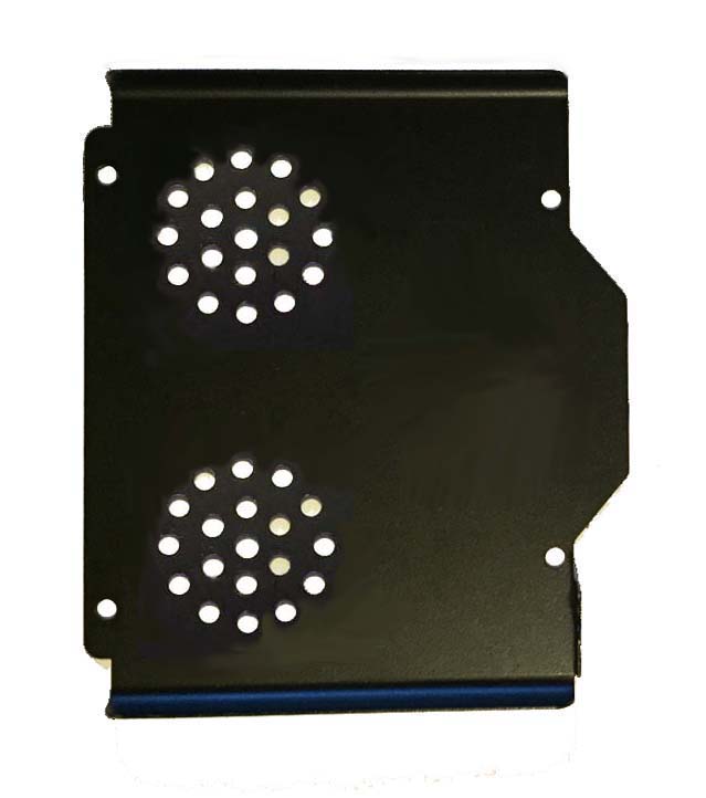
At the base of the thermostat, you will notice a small Ferrite Bead. Do not remove this component, as it prevents fan RF/static from entering into the receiver. References: Ferrite Bead EMI / RFI
Below shows the location of the KSD-01F as it is installed inside of a UV-2501 and similar mobile transceivers..
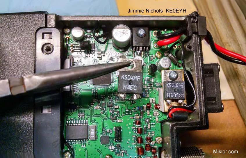
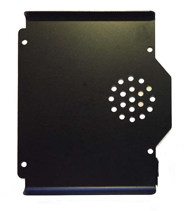
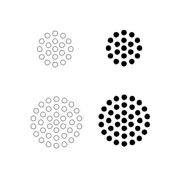
The Process The steps for the component replacement are very basic. - Trim the component leads to approximately 1/8" . - Remove the screw connecting current KSD-01F to the main board. - Using good soldering practices, unsolder the leads going to the thermostat to be replaced. Be extremely careful of soldering splashes. They don't play well with surface mount components. - Position the new KSD-01F in place. - Solder the red and black leads to the new component. - Tighten the retaining screw which also serves as the Ground connection. When the transmitter is keyed, the fan should turn on after approx 20 seconds. The fan will continue to run until the cool down threshold is met. This could take several minutes after the last transmission. Bottom Cover and Template For additional ventilation, you may want to consider adding some vents to the bottom cover. A circular pattern template can be found HERE. (Remember, Measure twice, cut once) Here are two examples that I personally used with my UV-5001.
|
|

