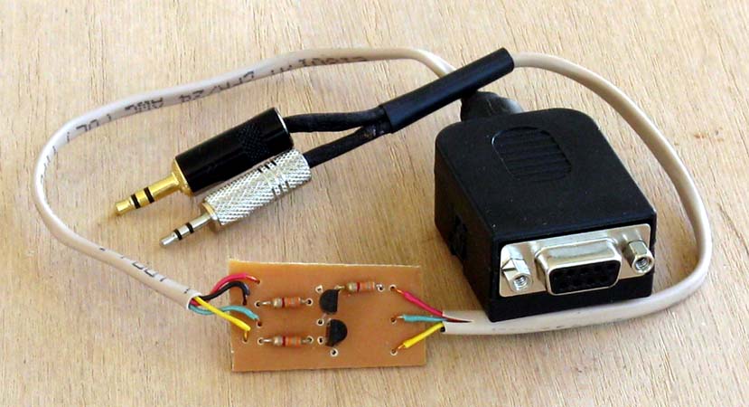
Build an RS-232 Serial Programming Cable
by Bob Desgrange KV4NF
No more hassle with USB ports.
|
 |
Project 232
Here's a level 2 project that eliminates the need for
the standard USB programming cable by using your
computer's COM Port (RS-232).
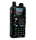
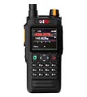
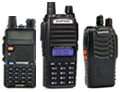
The example shown here is for a 2 pin Kenwood / Baofeng
connection, but can be adapted to any connector
requiring the standard GND, RxD, TxD configuration.
It's a Level 2 project because it involves the etching
of a small PC board, so prior PC board experience is a
plus.
The Parts List
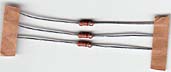
(2) 2N3904 transistors
(3) 3.3K resistors
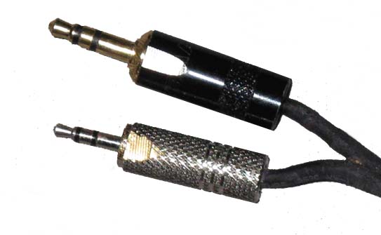
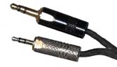
(1) 2.5 mm stereo plug
(1) 3.5 mm stereo plug
(1) RS232 DB-9 connector
To make the PC Board, you'll need:
- A LaserJet printer (not inkjet)
- Gloss photo paper
- Blank copper PC Board
- Ferric chloride etching solution (Amazon)
- Acetone (preferred), or nail polish remover
- Small Drill (Dremel)
- 1/32" (.81mm) drill bit size #67
If you are new to the world of Printer Circuit Boards,
here is a tutorial that will familiarize you with the
process:
-
How to Make a PCB at Home
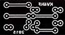
The PC Board
The first step is the creation of the board. A template (negative) can
be found
HERE (.docx)
and
HERE (.pdf)
Print this page using a Laser Jet printer and Glossy
Photo Paper. This is required as the toner will be
transferred from the Photo Paper to the copper board.
Use a standard household clothes iron to dry transfer the
image to PC board.
During this transfer process, the iron must at its highest setting - no steam - and apply a lot of pressure to the paper/PC board to ensure a good transfer of the plastic toner to the board.
Once cooled, slowly lift the paper from the board. The plastic toner and the first layer of paper should remain.
When done, remove the paper and plastic film with acetone (preferred), or nail polish remover.
Then etch the board with ferric chloride (Amazon).
Residue can be cleaned from the PCB using Acetone (nail
polish remover).
Important Note: Always take
precautions during the etching process. Rubber gloves
and eye protection are a must, as well as a dust mask
when drilling.
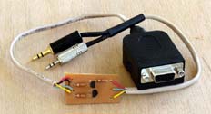
Drill the holes and then start soldering away.
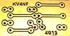
Below is the component layout on the PC board.
Click to enlarge |
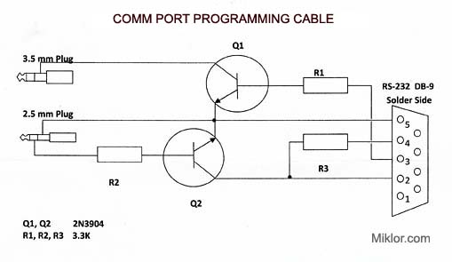
The schematic below shows the DB-9 connections as well
as the 2.5 and 3.5mm stereo plugs.
Depending on the stereo plugs used, you may need to
shave a little off the cases if the fit is too tight to
avoid damaging the jacks in the radio.
click to enlarge |
In Summary
I hope you had fun with this project. If you've never etched a PC
board before, this is a perfect beginner's project. Say goodbye to driver issues.
My thanks to Bob
Desgrange KV4NF for this
project.
Bob KV4NF
John 'Miklor'
|
|
|
|
|
|