1. |
|
Newest Radio and Firmware |
|
1.1 |
|
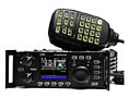
BTech UV-5X3 General Information |
| |
1.2 |
|
Firmware |
2. |
|
Transmitter and Receiver |
| |
2.1 |
|
I can't hear my local repeater (CTCSS) |
| |
2.2 |
|
I can't hear my signal, but I hear the
repeater squelch tail |
| |
2.3 |
|
Aircraft frequencies |
| |
2.4 |
|
Weather frequencies - NOAA / NWS |
| |
2.5 |
|
FM Radio broadcast cuts out |
| |
2.6 |
|
FM Broadcast overrides TDR (UV5R only) |
| |
2.7 |
|
Receiver Pulses when returning from a
received signal |
| |
2.8 |
|
Oscillator images / 'Birdies' |
| |
2.9 |
|
Selecting a Channel using the Keypad |
3. |
|
Programming |
| |
3.1 |
|
Software Compatibility - CHIRP |
| |
3.2 |
|
Channel is programmed but will not save |
| |
3.3 |
|
Storing the 7th / 8th digit of a frequency |
| |
3.4 |
|
Storing different frequencies in A and B |
| |
3.5 |
|
The purpose of 2 displays |
| |
3.6 |
|
Synchronizing display A and B |
| |
3.7 |
|
Disabling the transmitter for receive only
frequencies (NOAA) |
| |
3.8 |
|
Storing FM radio 65-108MHz channels in memory |
| |
3.9 |
|
Switching modes from VFO to MR |
| |
3.10 |
|
Radio transmits while Programming |
4. |
|
Scanning
|
| |
4.1 |
|
How to select channels to skip when scanning |
5. |
|
Tone Access
(CTCSS, DCS, DTMF)
|
| |
5.1 |
|
CTCSS / DCS tones - What are they |
| |
5.2 |
|
Tone Scanning |
| |
5.3 |
|
Tone Burst - 1000, 1450, 1750, 2100 Hz |
| |
5.4 |
|
DTMF tones |
6. |
|
Batteries and Accessories
|
| |
6.1 |
|
Battery Charging |
| |
6.2 |
|
Cables, antennas, Spkr/Micr interchangeability
|
| |
6.3 |
|
Is a radio case a good purchase |
| |
6.4 |
|
USB chargers |
| |
6.5 |
|
Charger Replacement |
| |
6.6 |
|
Optional Batteries |
| |
6.7 |
|
Build a USB charger for a 3800mAh battery side
jack |
| |
6.8 |
|
AC Adapter for charging a 3800mAh battery side
jack |
| |
6.9 |
|
AA / AAA Battery Cases |
| |
6.10 |
|
Battery Removal - Difficult |
| |
6.11 |
|
Battery Terminals get Hot when Transmitting |
7. |
|
Software, Cables &
Drivers
|
| |
7.1 |
|
Software selection |
| |
7.2 |
|
Error Messages |
| |
7.3 |
|
Programming Cable & Drivers |
| |
7.4 |
|
Genuine Programming Cables |
| |
7.5 |
|
Building Your Own Programming Cable |
| |
7.6 |
|
Frequency Expansion (hacking) |
8. |
|
Microphone and Audio issues
|
| |
8.1 |
|
No Transmit Audio |
| |
8.2 |
|
Low Transmit Audio |
| |
8.3 |
|
Less Microphone Sensitivity |
| |
8.4 |
|
PTT disabled when Spkr/Micr plugged in |
| |
8.5 |
|
External Speaker Microphone options |
9. |
|
Antenna Questions |
| |
9.1 |
|
Which antenna is best |
| |
9.2 |
|
SMA Antenna Connectors |
| |
9.3 |
|
Antenna doesn't screw in completely |
| |
9.4 |
|
Antenna identification |
10. |
|
Display Questions
|
| |
10.1 |
|
LCD turns dark |
| |
10.2 |
|
Display shows + and - at the same time |
| |
10.3 |
|
Battery Level Indicator |
| |
10.4 |
|
Display disappears if I wear sunglasses |
11. |
|
General Questions
|
| |
11.1 |
|
Radio shuts down |
| |
11.2 |
|
Did I get a used radio |
| |
11.3 |
|
Radio doesn't speak English |
| |
11.4 |
|
Keypad is Locked
 |
| |
|
|
|
| |
|
|
|
| |
|
|
 |
| |
|
|
Newest Radio and Firmware
|
| |
1.1 |
|
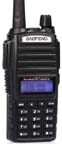
BTech UV-5X3 General Information
The UV-5X3 is a Tri-Band transceiver specifically designed to include the
222-225 MHz US ham band. The 5X3 filtering and band limits were designed
specifically for this type of operation.
This is not to be confused with software hacks that can artificially show
000-999 MHz on the LCD screen.
|
| |
1.2 |
|
Firmware - Can it be updated?
No. The firmware in these radios cannot be
updated. The microcontroller is an OTP type.
(One Time Programmable) Once 'flash' programmed
at the factory, it cannot be changed.
|
| |
|
|
Transmitter and Receiver
|
| |
2.1 |
|
I can't hear my local repeater (CTCSS)
Some Repeaters and Services require a CTCSS or
DCS tone for access but DO NOT transmit one back. If your display indicates there is an incoming signal but you hear no audio, you may have an incorrect or unnecessary RX tone set.
This can be tested by pressing the [MONI] button of the side of the radio. When in doubt, leave the
CTCSS or DCS tones set to OFF.
|
| |
2.2 |
|
I can't hear my signal, but I hear the
repeater squelch tail
The key here is that you can hear the repeater squelch tail.
You are too close to your receiver and over powering (de-sensing) it.
When this happens, you are blocking everything from your monitor.
1) Listen to your signal on simplex to verify you have audio.
2) Call someone on the repeater to verify your signal quality.
If they can hear you, then all is fine.
3) For testing using repeater frequencies, always set your monitor receiver to your transmitter's frequency, not the repeater's output signal.
|
| |
2.3 |
|
Can I receive Aircraft frequencies
No. They are out of the radio's frequency range.
|
| |
2.4 |
|
Can I receive Weather channels - NOAA / NWS
Yes. However, it cannot be put in a standby mode
and triggered by their 1050Hz alert tone.
|
| |
2.5 |
|
FM Broadcast Radio cuts out
The broadcast radio gives priority to an incoming VHF/UHF signal.
It returns back to FM Broadcast X seconds after the signal clears.
X is determined by the ABR setting. 0-10
To prevent the radio from switching, set VHF/UHF to an unused frequency.
|
| |
2.6 |
|
FM Broadcast overrides TDR
When receiving a commercial FM radio broadcast, the station
will only be interrupted when a signal on the
currently selected display (A or B) is received
regardless of the TDR-AB (Menu 34) setting.
|
| |
2.7 |
|
Receiver Pulses when returning from a received signal
This is a 'bug' in some firmware releases.
If Save (Menu 3) is set to 1, 2, 3 or 4 and ABR (Menu 6) is set to 9 or 10, a pulsing may occur on a broadcast FM signal when returning from a received signal interruption.
- Work Around: Set Save to OFF or ABR to 8 or less.
|
| |
2.8 |
|
Oscillator Images / 'Birdies'
The radio uses a 26MHz
reference oscillator. These have been known to
cause interference on some of the following frequencies
which are multiples of 26.
156.0, 234.0, 416.0, 442.0,
468.0, 494.0 MHz.
Household appliances are also notorious for
generating stray signals. Televisions,
computers, power supplies, chargers, etc.
If the 'birdie' is not present outside your
house, you will need to isolate the source
inside.
|
| |
2.9 |
|
Selecting a Channel using Keypad
Enter a three digit number to select
the desired channel.
- Enter 001 to select channel
1
- Enter 010 to select channel
10
- Enter 100 to select channel
100
|
| |
|
|
Programming
|
| |
3.1 |
|
Software Compatibility - CHIRP
When using CHIRP, Always
use the Latest Daily Build, available
HERE.
|
| |
3.2 |
|
Channel is programmed but will not save
There are three steps to the process:
1) You must be in the VFO/Frequency mode
2) Display A (top display) must be selected.
3) Channel must be empty before programming frequency data.
(use menu 28 to delete a channel) Refer to Programming Hints
|
| |
3.3 |
|
Storing the 7th / 8th digit of a frequency
The 5X3 will enter the 7th / 8th digits regardless of
the step setting.
462.716 = 462.71625
462.717 = 462.7175
462.718 = 462.71875 Rounded Up
462.719 = 462.71875 Rounded Down
- A tiny .25 / .5 / .75 kHz will appear to the right
on the LCD.
- The step setting only impacts the scanning
mode.
|
| |
3.4 |
|
Can I store different frequencies in A and B
No. There is only a single bank of 128 channels (0-127)
The same frequencies show in both displays A and B.
You can, however, change the way they appear. (Menu 21 & 22)
The display options are Frequency, Channel Name or Channel Number.
|
| |
3.5 |
|
The purpose of 2 displays
(A and B)
Dual Receive. You can set each to a different preprogrammed channel.
With TDR (Menu 7) turned on, your radio will sample between the
two frequencies and stop on whichever one has activity.
|
| |
3.6 |
|
Synchronizing display A and B
Display A and B can be synchronized to track
together by setting Menu 24 to SYNC. You can set one display for Frequency and the other display for Name
if desired.
|
| |
3.7 |
|
Disabling the transmitter for receive only
frequencies (NOAA)
This can be done using the transmit inhibit function of your software.
|
| |
3.8 |
|
Storing FM radio 65-108MHz channels in memory
This radio cannot store FM Broadcast channels in memory. You also cannot make this radio transmit on this band.
|
| |
3.9 |
|
Switching Modes from VFO (frequency) to MR
(channel)
- Press VFO / MR button
|
| |
3.10 |
|
Radio transmits while Programming
1 - Make sure the USB end is plugged in. Removing the USB end of a programming cable before unplugging the 2-pin plug from the radio (while it is still powered on) will cause the radio to transmit.
2 - Make sure a compatible device driver is installed (mostly related to Prolific type USB-to-TTL chips)
3 - Make sure that VOX is set to OFF.
|
| |
|
|
Scanning
|
| |
4.1 |
|
How to select channels to skip when scanning
Menu 33 allows you to add or delete channels
from the scan list.
|
| |
|
|
Tone Access (CTCSS, DCS, DTMF)
|
| |
5.1 |
|
What are CTCSS (PL) tones
A CTCSS is an 'Tone' sent along with your voice when transmitting.
They are used to access a specific repeater and block interference.
Visit
CTCSS for details.
|
| |
5.2 |
|
Tone Scanning
- Radio must be in VFO mode,
not MR (channel) mode.
To determine the Tone of an incoming signal,
perform the following:
MENU
1 0 (DCS) or 1 1 (CTCSS)
MENU
SCAN
A tiny CT should start flashing on the left side
of LCD.
- You can start the scan function prior a signal
being received.
- When a signal is detected, the scan will start automatically.
- When it finds the tone, it will beep and stop.
Note: The radio requires that Menu 10 (DCS) or Menu 11 (CTCSS) be set to something other than OFF to perform the scan.
|
| |
5.3 |
|
Tone Burst - 1000, 1450, 1750, 2100 Hz
If your repeater or network requires tone access
other than CTCSS/DCS, the following tone options
are available.
1000Hz = PTT + CALL
1450Hz = PTT + VFO/MR
1750Hz = PTT + A/B
2100Hz = PTT + BAND
|
| |
5.4 |
|
DTMF Tones
If you are using ANI codes to identify the radio
being received, the 5X3 now has the option to
not only send, but to display the codes being
sent by the other radio.
Although this is used mostly in commercial
applications, it is available in the 5X3 as
well.
|
| |
|
|
Batteries and Accessories
|
| |
6.1 |
|
Battery Charging
Do not leave the radio turned on while charging.
If the transceiver is powered on, it will continuously consume energy. The charger cannot detect when the battery has been fully charged and will fail to indicate correctly.
This could overcharge the battery and shorten its life.
|
| |
6.2 |
|
Cables, antennas, Spkr/Micr
interchangeability
Many Kenwood / Wouxun accessories are, such as Spkr/Micr,
Programming Cables, etc.
|
| |
6.3 |
|
Is a radio case a good purchase
If you carry your radio and keys in the same pocket, yes.
See Radio Shutdown under General Questions
below.
|
| |
6.4 |
|
USB chargers
These radios have a 7.4 volt battery while a USB port is only 5.0 volt.
There is not enough voltage to charge the battery. The standard charger supplies
8.4 volt during the charge cycle.
|
| |
6.5 |
|
Charger Replacement
The TYT BGC-F8 is a direct replacement and seems to be built more solidly. It is designed to use a 13.8Vdc input. With the proper cable, it can be used in the car to charge the battery while on the road.
|
| |
6.6 |
|
Optional Batteries
There are 3600 / 3800 mAh batteries, and AA /
AAA cases are available.
|
| |
6.7 |
|
Build a charger for a 3800mAh battery
This $5 regulated charger project will safely charge the BL-5L 3800mAh
battery.
Project Link
|
| |
6.8 |
|
AC Adapter for charging a 3800mAh battery side
jack
This AC charger will provide the regulated 8.4v required, but will
require an adapter.
eBay Charger Link
eBay Adapter Link
|
| |
6.9 |
|
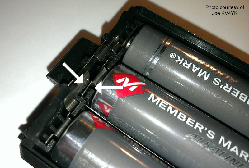
AA / AAA Battery Cases
This handheld requires 7.4V for proper operation.
The standard battery case will hold 6 AA or AAA cells.
The standard rechargeable battery provides 1.25V per cell.
This will provide the 7.4V needed. (6x1.25=7.5V)
Note 1: Most Alkaline batteries provide 1.5V per cell. (6x1.5=9.0V)
This will create an Over Voltage condition and the radio's protection circuit will cause the radio to not transmit.
To prevent this from occurring, replace one of the cells with a spacer or 'dummy' cell. This will drop the voltage to (5x1.5=7.5V) for proper operation. They can be found on eBay by searching "AA dummy battery"
Note 2: Some battery cases have very close tolerances. Although this is normally not an issue, you may want to slide a thin piece of paper or cardboard between the contacts to prevent a short if something should slip out of place.
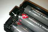
click to enlarge
|
|
| |
6.10 |
|
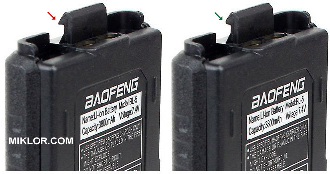
Battery Removal - Difficult
Some batteries ship with a sharp edge on the clip that holds the battery in place. This can be smoothed down with fine sandpaper. Only take off a small amount at a time.
click to enlarge
|
|
| |
6.11 |
|
Battery Terminals get Hot when Transmitting
When you touch the batteries ground charging
tab, you are also providing an RF ground as well
with your hand. This is an RF burn.
|
| |
|
|
Software, Cables & Drivers
|
| |
7.1 |
|
Software selection
The software for this model is CHIRP.
Refer to item (3.1) above.
|
| |
7.2 |
|
Error Messages
There are several common error messages
that could appear
when programming via software.
A list of these error messages, their definition
and recovery can be found at
Error Messages.
|
| |
7.3 |
|
Programming Cable / Drivers
This is one of the major frustrations with
generic, low cost programming cables.
Many generic cables use Prolific chip clones/copies.
When plugged into a USB slot, Windows will load the latest driver.
These drivers have been updated to reject cables using cloned chips.
These cables will work fine, but only if the proper
backdated driver is installed.
This is covered in detail at
USB Cable Drivers.
|
| |
7.4 |
|
Genuine Programming Cable
Programming cables utilizing an
FTDI chip will work with no problems.
These cables are truly "Plug 'n Play". Call your local dealer before ordering to confirm chip set.
|
| |
7.5 |
|
Building Your Own Programming Cable
Another option is to build your own programming
cable.
The Diagrams and Procedures can be found at:
USB to 2 Pin
- Baofeng / Kenwood
General Technical Information
|
| |
7.6 |
|
Frequency Expansion (hacking)
There is software available that will allow you to enter any number you wish.
However, even though the number shows in the display, internal filtering
of the radio prevents both TX & RX operation on these frequencies and
may cause irreversible damage to your radio.
|
| |
|
|
Microphone and Audio Issues
|
| |
8.1 |
|
No Transmit Audio
First, confirm you have no TX audio by listening to your signal on Simplex. If you experience no audio, the microphone jack might be stuck open with debris. Trim a Q-Tip to fit the microphone jack opening and dampen with denatured alcohol to clean the jack contacts. Allow ample time to dry.
If this doesn't resolve the issue, you may need to go one step further, as shown at this
YouTube Video.
|
| |
8.2 |
|
Low Transmit Audio
Here's are some suggestions:
1) Talk directly into the radio, within one inch.
2) Try an external spkr/mic to confirm problem is the mic.
3) Blow compressed air into the spkr/mic jack.
4) If you have an external spkr/mic, plug it in and out a few times.
The issue might be a dirty connector.
5) Ham Bands Only - Set to Wide Band. 5 kHz (Menu 5=W)
Note: Some have reported the need to open up the microphone hole in the plastic case. This can be done by CAREFULLY using a 3/64" drill bit and twisting it slowly by hand to clear out the opening, but avoid touching the microphone
element. There is approx 1/16" clearance between the inside of the case and the microphone element.
|
| |
8.3 |
|
Less Microphone Sensitivity
Unlike Ham equipment, many of these radios were initially designed
for commercial use. This was to block out background noise in an industrial environment.
Talking right into the face of the radio cures most audio weakness.
Do not confuse the audio of a handheld with that
of a smart phone that can hear a pin drop in the
next room.
|
| |
8.4 |
|
Is PTT disabled when Spkr/Micr plugged in
No. Even with a Spkr/Mic plugged in, the PTT switch is still physically connected. This is true for most handhelds.
|
| |
8.5 |
|
External Speaker Microphone (ESM) options
There are two optional available.
1.
Single PTT ESM
Transmits on selected display.
2.
Dual PTT ESM
Functions as a standard single PTT Spkr/Micr.
Only the Lower Side PTT will function. Top PTT button has no effect.
Using a Dual PTT
Spkr/Micr with a UV5R (or any radio with a
single PTT) will not create a new Dual PTT
function for that radio.
|
| |
|
|
Antenna Questions
|
| |
9.1 |
|
Which antenna is best?
It's all personal preference, but a good rule of thumb is:
The longer the radiator, the better the range, especially on transmit.
Short stubby antennas use a coil to match TX to 50 ohm, not radiate.
The closer to 1/4 wavelength in the air, the better the performance.
Field test results using 31 popular antennas can be found
at
Field Tests.
An overview of antenna types available can be
found at
Best Antenna.
|
| |
9.2 |
|
SMA Antenna Connectors
There are several varieties of SMA connector.
Male, Female, Reverse Polarity, etc.
Diagrams of these varieties can be found at
SMA
Antenna
|
| |
9.3 |
|
Antenna doesn't screw in completely
This is not uncommon on some aftermarket antennas. If your antenna
doesn't come with a rubber spacer to fill the
gap, you can purchase a thin 5/8" OD rubber O-Ring. Take your HT with you to the hardware store to assure the proper fit.
Additional information can be found at
Extended Threads
|
| |
9.4 |
|
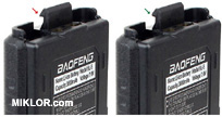
Antenna identification
The 5x3 is a tri band radio that includes two
antennas. The identification of the antennas can
be done in two ways.
- At the base of the antennas are frequency
identification bands. The white ring identifies
the single band antenna for the 220mhz band. The
black ring identifies the dual band 2m/70cm band
antenna.
- The single band 220mhz antenna is physically
1/4 inch shorter than the dual band antenna.
|
| |
|
|
Display Questions
|
| |
10.1 |
|
LCD turns dark
This is to be expected from a small radio.
5 watts creates a lot of heat in a small unvented area.
The newer 8 watt F8HP will heat up even quicker.
Give it time to cool down and the LCD will return to normal.
The same occurs if you leave the unit in the car on a hot day.
Run low power whenever possible. This will also extend battery life.
|
| |
10.2 |
|
Display shows + and - at the same time
In Channel Mode this is normal when the TX/RX frequencies differ.
In Frequency Mode + or - is displayed based on Menu 25 (Shift)
If TX and RX are the same (simplex) the + - indicator does not display.
|
| |
10.3 |
|
Translating the Battery Level Indicator
Tests have shown the following: (tests by Phil Souza)
Full charge (approx 8.32 volts) 3 bars
Battery drops to 7.09 volts, 2 bars
Battery drops to 6.73 volts, 1 bar
Battery drops to 6.29 volts, 0 bars
Battery drops to 5.91 volts,
the radio announces "low voltage" until the battery expires.
Note: Volume must be turned up to hear the battery warning.
Note: Measurements can vary based on temperature and load.
|
| |
10.4 |
|
Display disappears if I wear sunglasses
LCDs function by polarizing the liquid crystal elements in the display.
Polarized sunglasses will react to the polarized lens.
LCD Wiki
|
| |
|
|
General Questions
|
| |
11.1 |
|
Radio shuts down
A case is recommended if you carry your radio and keys in the same pocket. If the charging contacts are shorted, the battery goes into the protection mode. There will be no damage to the radio, but it will power off. To reset the protection mode, the battery must be removed and reinserted.
Note: If you carry a spare battery, place it in a
small plastic bag for protection.
|
| |
11.2 |
|
Did I get a used radio
Some radios come with some
channels pre-programmed. These are channels used for factory testing.
The easiest way to remove them is:
- Press Menu, 42 (Reset), Menu, ALL, Menu.
|
| |
11.3 |
|
Radio doesn't speak English
Press Menu, 14, Menu, Make selection, Menu
Options are CHI / ENG / OFF
|
| |
11.4 |
|
Locking / Unlocking the Keypad
Hold the #
 key in for
approximately 3 seconds. key in for
approximately 3 seconds.
Pressing it quickly alternates TX power level.
|
| |
|
|
|